|
Patterns, Castings vs Machined Parts - Codes, Numbers and Dates
- click on image to enlarge |
|---|
| Patterns and Castings |
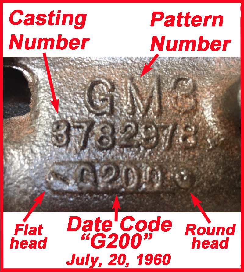
Several of the powertrain components were, or incorporated, parts made in a foundry. Some were cast in steel (transmission and differential cases, exhaust manifolds), others in aluminum (engine blocks, heads, and rear housing), and carried codes, part numbers and/or dates of manufacture. To make these components, molds were created by packing sand around a pattern (prototype) of the part to be produced. Each component was embossed with a unique part number, but there were multiple copies of the pattern (to maximize production rate), and each pattern carried a unique identifier, such as GM1, GM2, GM3, etc. Thus, there would be no difference between components with different pattern numbers but the same part number. Additionally, each casting was embossed with a casting date.
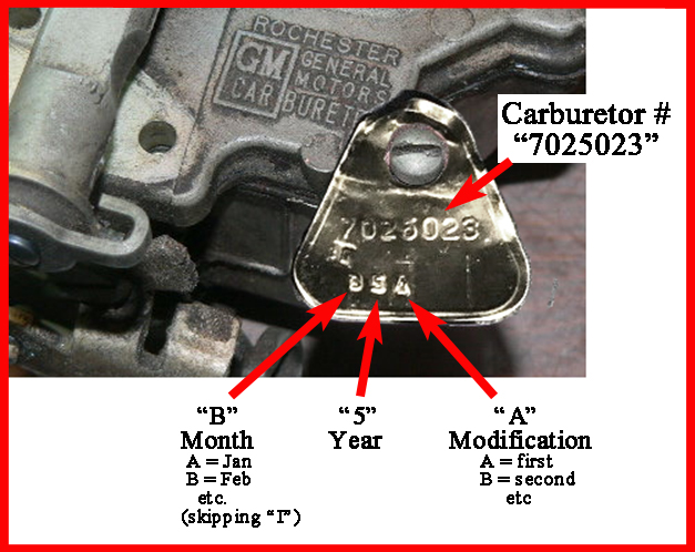
Casting dates - In the casting date, the month is identified by a letter
A = Jan, B = Feb, C = Mar, D = Apr, E = May, F = Jun,
G = Jul, H = Aug, I = Sep, J = Oct, K = Nov, L = Dec
The month is followed by the day, and then a single digit for the year.
 The codes themselves were on embossed plates screwed to the pattern, allowing the date code to be changed day to day. The shape of the screw heads on either side of the date code signifies which shift poured the casting: 1st shift with two flat-head, 3rd shift with two round-head screws, and 2nd shift with one of each. The codes themselves were on embossed plates screwed to the pattern, allowing the date code to be changed day to day. The shape of the screw heads on either side of the date code signifies which shift poured the casting: 1st shift with two flat-head, 3rd shift with two round-head screws, and 2nd shift with one of each. |
| Machined parts |
A cast usually was subsequently machined to the final specifications; and the same pattern could yield different final forms, each with its own machined part number. These are the part numbers usually found in the Parts and Accessories catalogs (but not on the part itself). The machined parts were engraved with production codes and dates, which are decribed below. |
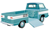
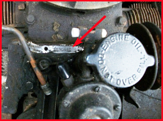
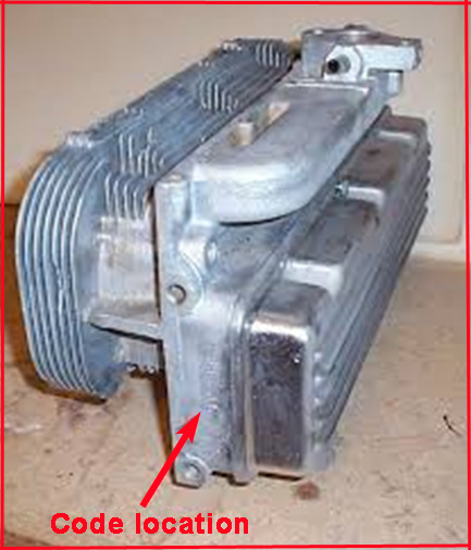
 Transmissions Where to find the ID codes - click on image to enlarge
On '61 & '62 MTs the ID code is on the differential mounting boss, upper left side 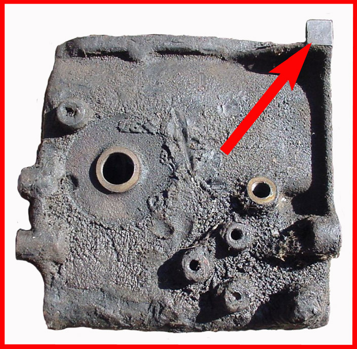
On '63 - '65 MTs the ID code is on boss, lower left side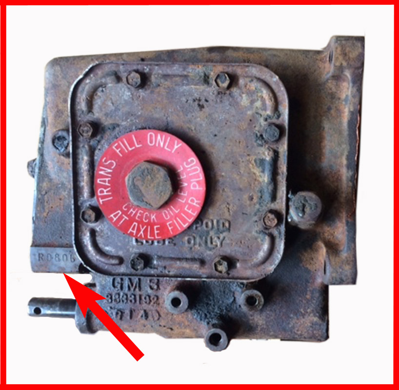
On '61 - '65 PGs the ID code is on the right hand side of casting and middle pan mounting boss.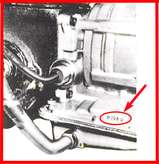
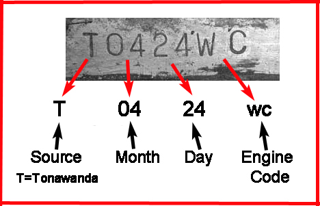
'61 MT codes include the type code and assembly month and day.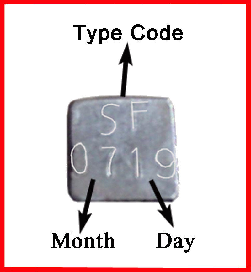
'63 - '65 MT codes include type code and assembly month and day. 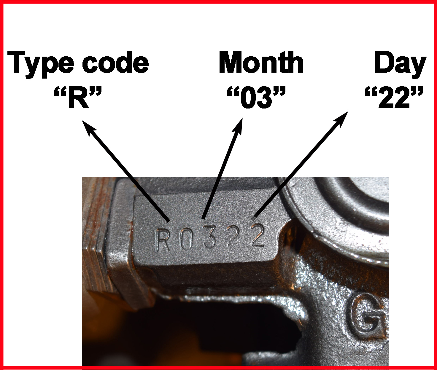
Codes of PG transmissions have the type code and the assembly, month, day and shift (D=day or N=night)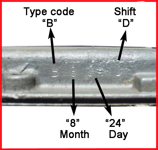
Transmission Sources: MTs from Saginaw; PG from Toledo
Some other distinquishing features
A backup light was never used in the FC, the hole in the case for the switch was usually drilled but plugged, as in this transmission. 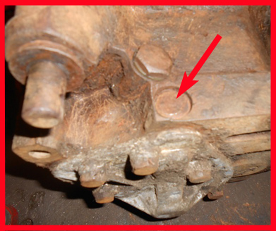
In 1964 the lube drain hole (red circle) was eliminated from the 4-speed transmission. The green circle is the differential drain hole. 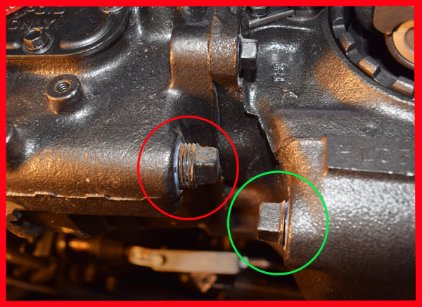
|
|---|
1961 Transmissions
|
| Code |
Application |
Part # |
Case # |
Gear ratio, notes, etc. |
|---|
| ST |
3 Speed MT
|
The standard equipment 3 speed manual transmission was the only transmissions to have a large, stamped steel access panel on the top. |
|
3785446 |
3784344
|
1st-3.50 2nd-1.99 3rd-1.00 rev-3.97
(1961 AM) |
| SF |
4 Speed MT
|
See table below for detailed descriptions of 4 speed transmissions |
| |
3785452*
(early) |
3782978* |
1st-4.26 2nd-2.35 3rd-1.48 4th-1.00 rev-4.27 |
| 3785452 - was the "1st design" '61 4sp transmission. It's identified in the earliest P&A catalogs and the engineering documents indicate it to have a 4.26 1st gear; changes to the engineering document correspond with those described in Technical Service Bulletin #690. [See notes below the 4 Speed Transmission table about earlier prototype 4.66 transmissions.] |
|
3788154*
(late) |
3788155 |
1st-3.65, 2nd-2.35, 3rd-1.44, 4th-1.00, rev-3.66 |
| 3788154 - was the "2nd design" '61 - early '62 4sp. This is the part number given in both the '61 and '62 assembly manuals. It has the 3.65 1st gear. This transmission was originally used for the passenger car only and was then used in the FC also, as reflected in the usage shown in the '61and '62 P&A catalogs. |
| B | Powerglide
|
Powerglide transmissions were delivered to the assembly line under a transaxle part number (as a transmission + differential assembly).¥ |
|
3795640 transaxle assembly (1961 AM); 3788375= transmission (P&A 616-1 12/1960) |
| ¥Manual transmissions and differentials were shipped directly from their sources to the assembly lines in Flint and St Louis. However, powerglide rear axles from Buffalo went first to Toledo to be mated with powerglide transmissions and converters so that they could be tested and the converter balanced. Only then were the complete assembly units shipped to the assembly lines. |
1962 Transmissions
|
|---|
| Code |
Application |
Part # |
Case # |
Gear ratio, notes, etc. |
|---|
|
| ST |
3 Speed MT¥
|
In order to raise the level of the lubrication in the transmission, the lube filler hole was to be moved upward 1" as a running change was implemented in January 1962. The hole diameter also would be increased from ½" to 7⁄8". Until modified parts were available, '62 FCs with the 3784344 case would receive a 45O "L" tube extension (444058) at the fill tube hole (1962 AM, Central Office Advanced Information Notice A.I. 62-13; 3/12/62) |
| | 3826177 |
3784344 |
3.50, 1.99, 1.00 rev-3.97 |
| SF |
4 Speed MT¥
| See table below for detailed descriptions of 4 speed transmissions |
| | 3788154*
early |
3788155 |
3788154 was continued from previous year |
3799363*
late |
3799364 |
3799363 superceded 3788154 and was used for the remainder of '62 through '63. (P&A 621A 10/61) |
| B | Powerglide
|
As explained for 1961, powerglide transmissions were delivered to the assembly line under a complete transaxle assembly. |
|
3745640 = transaxle assembly 3788375 = transmission (P&A 34 Oct '62) |
| ¥Introduced as a mid-1962 change for manual transmissions was the red filler hole plug gasket with the "Trans. Fill Only" message. |
1963 Transmissions
|
| Code |
Application |
Part # |
Case # |
Gear ratio, notes, etc. |
|---|
| S |
3 Speed MT
|
In light of the mid-'62 change described above, the 1963 AM may be incorrect in showing 3826177 continued from previous year. P&A-10/63 identifies the case as 3826176. |
|
| [3826177-?] |
3826176 | 3.50, 1.99, 1.00 rev-3.97 |
R |
4 Speed MT
| See table below for detailed descriptions of 4 speed transmissions |
| | 3799363* |
3799364 |
3799363 continued from previous year (1963 AM; P&A-34 10/62) |
| B | Powerglide
| As explained for 1961, powerglide transmissions were delivered to the assembly line under a complete transaxle assembly |
|
3745640 = transaxle assembly (1963 AM) 3788375 = transmission; |
1964-65 Transmissions
|
| Code |
Application |
Part # |
Case # |
Gear ratio, notes, etc. |
|---|
| S |
3 Speed MT
| 3840785 |
3849447 |
(1964 AM; P&A-34 10/63) |
| R |
4 Speed MT
|
Major design changes were implements in 1964 and carried forward for 1965. See table below for detailed descriptions of 4 speed transmissions. |
| | 3837288*
early '64
|
3833192* |
3837288 was the "First design ", a modification of #3833191*, the '64 car 4 speed that used a larger diameter 14 spline input shaft. (1964 AM) |
3864460*
late '64 - '65
| 3833192* |
3864460 was the "Second design" (1965 AM; P&A-34 10/65) |
| B | Powerglide
| As explained for 1961, powerglide transmissions were delivered to the assembly line under a complete transaxle assembly |
|
|
| 1964 |
3838478 = (transaxle assembly (1964 AM) 3857347 = transmission (P&A-34 10/65) |
| 1965 |
3857445 = transaxle assembly (1965 AM) 3866774 = transmissio; (P&A-34 10/65) |
| 4 Speed Transmission Component Summary1 |
| component |
Early '612 |
Late '61 - Early'623 |
Late '62 - '63 |
Early '64 |
Late '64 - '65 |
| Transmission part # |
3785452 |
3788154 |
3799363 |
3837288 |
3864460 |
| Case # |
3782978 |
3788155 |
3799364 |
3833192 |
| Backup light boss4 |
undrilled |
drilled and threaded but plugged |
undrilled |
| Lube drain hole |
present |
absent |
| Lube filler hole dia. |
1/2" |
7/8" |
| gear ratio |
1st-4.26 2nd-2.35 3rd-1.48 4th-1.00 rev-4.27 |
1st-3.65, 2nd-2.35, 3rd-1.44, 4th-1.00, rev-3.658 |
| Input shaft |
3785456
12 splines |
3840297
14 splines |
| Main shaft |
3785453 |
3813663 |
3852240 |
| Main shaft bearing |
907259 |
907443 |
| Countershaft |
3775061 (teeth: 30,27,21,14,15) |
| Countershaft gear |
3784644 |
6257855 |
3851512 |
| Clutch gear & synchronizer assy |
3785455
(30o bevel angle) |
3814014
(30o bevel angle) |
3840294
(30o bevel angle) |
3851508
(45o bevel angle) |
| 1st gear (31 teeth) |
3775090 |
38522445 |
| 2nd gear |
3775093
26 teeth |
6257856
28 teeth |
38373005
28 teeth |
| 2nd gear thrst brg |
9415297 |
-- |
-- |
| 1st/2nd synch assy |
3780688 |
38139015 |
| 1st/2nd blocking ring |
3779482 |
3813902 |
| 3rd gear (22 teeth) |
3780252 |
3821380 |
3837298 |
| 3rd/4th synch assy |
3779484
|
3813904
|
3794203 |
| 3rd/4th blocking ring |
3779485 |
3813905 |
3849964 |
| reverse idler |
3780111 |
3833198
|
| reverse inhibitor assy |
3775070 |
? |
? |
Notes
1 - Data was drawn from Assembly Manuals, P&A catalogs (cautiously) Engineering drawings and documents, and other GM documents, as well as Craig Nicol's article on 4-Speed transmissions in the Oct 2003 CORSA Communique, and his separate table of 4 speed transmissions. This reexamination yielded some differences from Nicol's in the inclusion of 3788154 as the FC 4-speed in '61 - '62, and in part numbers in a few places.
2- The Engineering drawings also include two other assemblies with the 4.26 ratio first gear. 3772149* is the earliest drawing of which other assemblies were modifications, including 3785452 and 3772157*, the latter appears to be an early prototype FC 4 speed with a 28-tooth 2nd gear. Only 3785452 was put into production.
3- The rationale for 3788154 is described above in the 1961 transmissions section.
4- A hole for the unused backup light switch was undrilled in 4.26-geared transmissions but drilled and sealed with a "Welch plug" in 3.65 transmissions (although possibly undrilled occasionally; Kirkman, CA 1994 vol 23-1;). The boss was again undrilled in the late version 3864460 transnmissions.
5- In the 1993 Vol 21(#2) issue of CorvanAntics, Bob Helt reported that all of the '64 - '65 4-speed FC transmissions that he had inspected were "hybrids" with late style 3rd and 4th (clutch) gears but with the earlier ('61-'63) 1st and 2nd gear components. Why so was a "mystery".
|
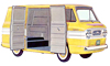
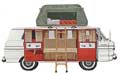
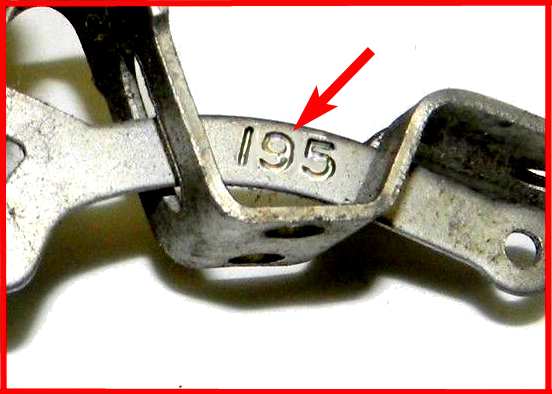
 Differentials (Rear axles) Where to find the ID codes - click images to enlarge
Case numbers are on the upper bellhousing cover flange 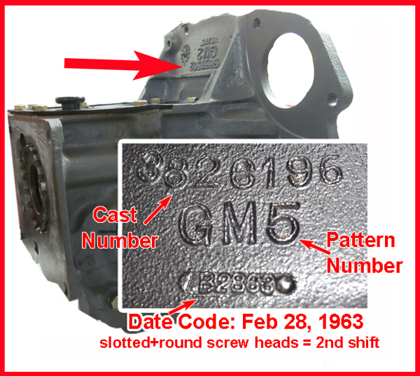
For '61 -'64 differentials, ID codes are on flat retangular boss on lower feft side.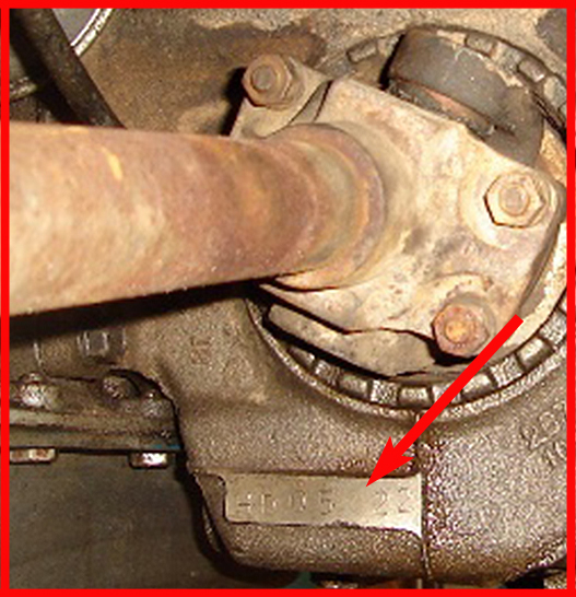
For '65 differentials, ID codes are lightly engraved on right side of case .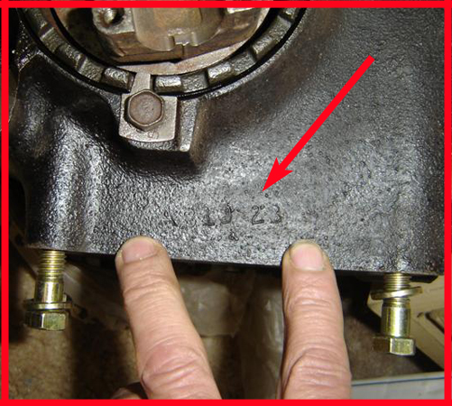
Example late code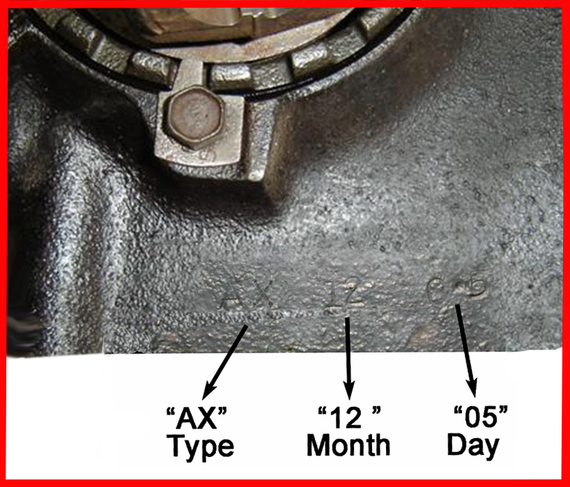
Example early code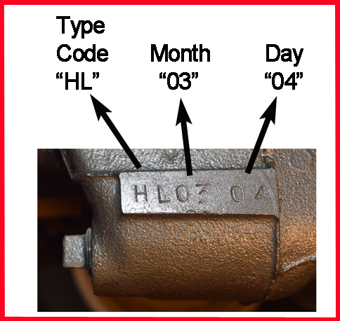
In 1964 the lube drain hole (green circle) was eliminated. The red circle is the transmission drain hole.
Parts and Accessory catalogs, section 5.505, generally give part numbers for differential cases not the complete differential assemblies. Assembly Manuals give the numbers for either the complete differential (for manual transmssions) or for differential+transmission assemblies (for powerglides). Data here is supplemented with information from other sources, including engineering drawings and documents and other GM documents
|
|---|
1961 Differentials
|
| Code | Application | Carrier |
Differential assembly (DA) and/or Transaxle assembly (TA) |
|---|
| BQ | 3.27 with MT |
3780270 |
3779576 DA (P&A 616-1 12/60) |
| BC | 3.27 with PG |
3780272* |
3783257 TA (P&A 616-1 12/60) |
| The differential with a 3.27 gear ratio was available only for a while in the beginning of the 1961 model year. |
| BL | 3.89 with MT |
3780270 |
3783095 DA (1961 AM) |
| BY | 3.89 with PG |
3780272* |
3795640 TA (1961 AM) |
| |
1962 Differentials - All 3.89:1 ratio
|
| Code | Application | Carrier |
Differential assembly (DA) and/or Transaxle assembly (TA) |
|---|
| HE | MT |
3826196*
(P&A 34 10/62) |
E - 3783095 - DA ('62 AM) |
| L- 3826217 - DA ('62 AM) |
| HF | PG |
3780272*
(P&A 34 10/62) |
3780272 - TA (P&A 621A 10/61) |
| HL |
Posi with MT |
3826196* |
3826221 - DA (1962 AM) |
| HM |
Posi with PG |
3780272* |
3826211 - TA (1962 AM) |
| A mid-1962 model year change was increasing the diameter of the differential filler hole from 1/2" to 3/4" pipe thread. This was done at the same time that the filler hole of the 3-speed MT was elevated an inch and increased to a 7/8" diameter. (1962 AM, Central Office Advanced Information Notice A.I. 62-13; 3/12/62)
|
1963 Differentials - All 3.89:1 ratio |
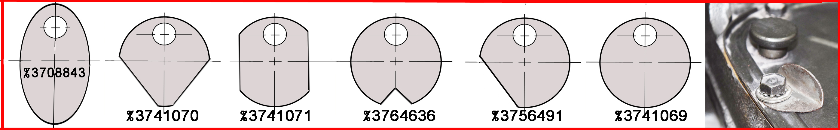
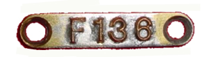
At least for '63 and '64, differential assemblies were identified with a small metal tab of a specific shape artached under a bolt of the differential cover. Most of these probably are long gone. 1963 coding was as follows:
Tag 3741069 -
3.89 axles (HE, HF, HL, HM);
Tag 3756491 - 3.55 axles (HB, HJ, HJ and HK)
Tag 3741070 - 3.08 axles (HN, HP); no tag - 3.27 axles (HA, HC, HG, HH) (Axle ID Chart 3826800*)
|
| Code | Application | Carrier |
Differential assembly (DA) and/or Transaxle assembly (TA) |
|---|
| HE | MT
|
3826196* (P&A 34 10/62)
|
3826217 = DA ('63 AM; AIDC) |
| HF | PG |
Early - 3794252* |
3795640 = TA ('63 AM) |
| Late - 3826197* (P&A 34 10/63) |
3794236 = DA (AIDC) 3794246 = TA (AIDC) |
| HL |
Posi with MT |
3826196* (P&A 34 10/62) |
3826221 = DA ('63 AM; AIDC ) |
| HM |
Posi with PG |
3826197* (P&A 34 10/63) |
3794248 = DA (AIDC) 3794240 = TA ('63 AM; AIDC) |
|
Information sources: '63 Assembly Manual (AM), Parts and Accessory (P&A) catalogs, and engineering Axle ID Chart (AIDC)#3826800.
|
|
1964 Differentials - All 3.55:1 ratio; carrier with mounting pad for car leaf spring
|
| Code | Application | Carrier |
Differential assembly (DA) and/or Transaxle assembly (TA) |
|---|
| HQ |
MT |
Early -3848104* (P&A 34 10/63),
Late - 3856267* (P&A 34 10/65 ) |
L-3856262= DA ('64 AM; F&P) |
|
| HS |
PG |
3848105* (P&A 34 10/63), ID tag 3741070 |
3838479= DA (F&P); 3838478 = TA ('64 AM; F&P) |
| HR |
Posi with MT |
? |
3856265 = DA ('64 AM; F&P) |
|
| HT |
Posi with PG |
? |
3838482 = DA (DIDC; F&P) tag 3741070
3838481 = TA ('64 AM; F&P) |
Information sources: GM Facilities & Production Planning Department document dated 3-17-1964 (F&P); '64 Assembly manual (AM); Parts and Accessory (P&A) catalogs; engineering Differential ID Chart (DIDC) #3849014. ID tag numbers come from Differential Carrier Assembly chart #3849014
|
1965 Differentials - All 3.55:1 ratio |
| Code | Application | Carrier |
Differential assembly (DA)and/or Transaxle assembly (TA) |
|---|
| AV |
MT |
3857450* |
3857446 = DA (1965 AM; DCAC2) |
| AX |
PG |
3857451* |
3857447 = DA (DCAC3); 3857445 =TA (1965 AM) |
| AW |
Posi with MT |
3857450* |
3864308 = DA ('65 AM) |
|
| AY |
Posi with PG |
3857451* |
3864310* = DA (DCAC3) |
|
Is 3864309 a PG or MT differential? The '65 AM says PG, the engineering document for the unit says MT; I have favored the engineering document, and substituted the corresponding PG unit 3864310. Reference also Differential Carrier Assembly Charts 3868792* (DCAC2) and 38687933* (DCAC3). |
|
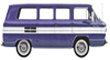
Generators and Regulators
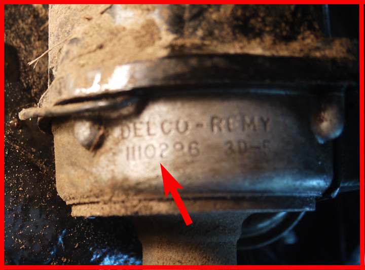
(Alternators in '65) Where to find the ID codes - click on image to enlarge
Generator part number and date code are stamped on the red Delco-Remy tag.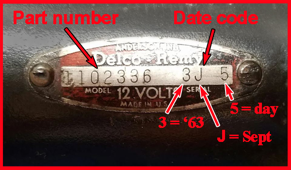
Regulator part number is stamped on mounting bracket.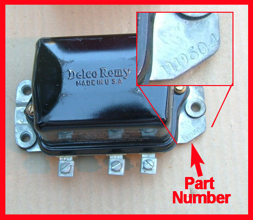
Alternator part number and date code are stamped on the alternator housing.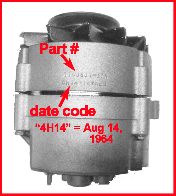
In the date code, the Year is:
1 = 1961, 2 = 1962, 3 = 1963,
4 = 1964, 5 = 1965
followed by the month, which is abbreviated as a letter:
A = Jan, B = Feb, C = Mar,
D = Apr, E = May, F = Jun,
G = Jul, H = Aug, J = Sep,
K = Oct, L = Nov, M = Dec
which is followed by the day.
|
1961-63 Generators & Regulators |
| Generator Part # |
Amps |
stock/option |
Regulator |
| 1102227 |
30A |
stock |
1119001 |
| 1105135 |
35A L.C.I. |
FAO 650 / RPO K71 |
'61: 1119635*
'62-'63: 1119604 |
The 35 Amp LCI generator was intended for FCs that had a high current demand, such as ambulances, emergency vans and other service vehicles. LCI stands for "Low Cut-In". Generator cut-in is often defined as the speed at which the generator produces a voltage equal to that of the fully charged battery. The specifications show that the 5135 unit could produce 14 Volts (and 35 Amp) at 1730 RPM, versus 2230 RPM (and 30 Amp) for the stock generator. In order to produce higher current at lower RPM, a larger generator with more armature windings is needed, and this is well reflected in the substantial weight of the 5135. |
1964 Generators & Regulators |
| Generator Part # |
Amps |
stock/option |
Regulator |
| 1102336 |
35A |
stock |
1119305* |
| 1105135 |
35A L.C.I. |
RPO K71 |
1119604 |
|
1965 Alternators & Regulators |
| Generator Part # |
Amps |
stock/option |
Regulator |
| 1100639 |
37A |
stock |
1119515* |
| 1100698 |
47A |
RPO K84 |
1119519 |
|